Gamma Correction provides a more accurate view of visual experience
So that’s the definition of what “response time” actually means officially. In 2020 a video by a5hun at Aperturegrille on YouTube, and then later discussed at length by Hardware Unboxed and TFTCentral highlighted a flaw with the traditional measurement method. This old method did not account for the impact of display gamma, and so the way the tolerance levels of 10% and 90% were used led to some issues. 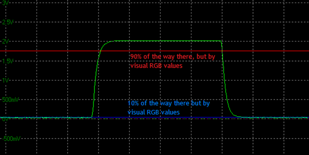
You can refer back to the resource linked above for a lot more information, but a better method was suggested that would “gamma correct” the measurements and therefore provide a more realistic reflection of the performance from a visual point of view. The tolerance levels of 10 and 90% can still be kept if desired, but now the measurements are based on the actual visual RGB values instead of just the voltage that is converted from the light output. This removes the error with just referring to voltage scales on the data that were being used before in the “traditional response time method”.
This is useful to provide a more complete view of what you would see in real use and we would recommend leaving “gamma corrected response times” enabled in the software, unless you have some specific reason to measure using the old traditional method.
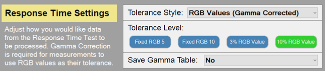
- Select the test settings menu > switch to advanced mode at the top > in response time settings section select tolerance style as “RGB values (Gamma corrected)l” > select “10% light level” option as shown below.
From there the question becomes – what is a reasonable tolerance / offset level to use, if any, and which part of the response curve do you want to capture?