What do we mean by display pixel “response time”? – it might not be as simple as you think
First of all, we should consider what the term “response time” really means in the display market. It is not as simple as just saying “it’s the time it takes for a pixel to change from one colour to another”. That’s not actually what the term “response time” means strictly.
For over 20 years the definition of response time in the display market is actually, in simple terms: “the time taken to switch between two colours, allowing for a small leeway of 10% either side”. Put another way, “It’s the time to go from close to the starting colour, to close to the end colour”.
Actually we are measuring changes in grey shade of the pixels based on how much light they let through from the backlight (for LCD displays at least), from RGB 0 (black) to 255 (white). The colour filters are applied on top so from now on we will talk about this as changes in grey shade, which is where the term “grey to grey” (G2G / GtG) comes from in the market.
Represented on a graph measuring the change, it would look something like this: 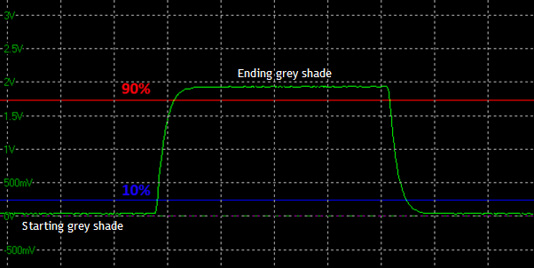
Where the bottom green line of the graph is the darker grey shade it is changing FROM, and the top green line represents the lighter grey shade it is changing TO. The light from the display is picked up by a photosensor or similar device and converted to a voltage on the graph.
The time it takes to switch from the bottom green line (dark shade) to the top green line (light shade) would be the full transition time of the change, but actually the definition of the “response time”, as defined a long time ago and uniformly adopted by panel and display manufacturers, is the time it takes to change within a 10% tolerance of either shade. That’s represented by the 10% blue line close to the starting grey shade, and to the 90% red line which is close to the end grey shade. That’s what the term “response time” officially means in the display industry.
The reasons for this being adopted were:
Because having a modest 10% tolerance level is widely adopted in various areas of electronics and measurement, so it seems to make sense to do the same here
It helps to some degree reflect a more realistic view of the time it takes to get “close enough” to the desired colour from a visual point of view. For instance, if you’re transitioning to black, there is a point where very dark grey is “close enough” to look visually indistinguishable and very similar. A small tolerance accounts for this leeway in what you see visually. This is a good thing for displays as after all, it’s all about what you see as a user.
It also helps avoid some complications with measurement methods, removing any noise or variation as you get close to certain shades, especially towards black.
Let’s call this the “traditional response time” for reference.
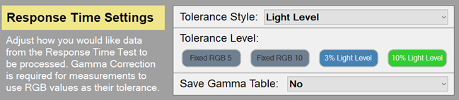
If you want to, you can measure using this method from OSRTT by:
- Select the test settings menu > switch to advanced mode at the top > in response time settings section select tolerance style as “light level” > select “10% light level” option as shown below.
We do not believe that this is the best way to present this measurement data any more, and would advise using the other methods discussed below. It is included for completeness and reference.